Hardware Hacking
About custom hardware extensions, see also Kernel interface
Contents
Official Hackers Manual
There is a LOT of great information in this: Pandora Hackers Manual v1.01 by MWeston v1.00 by MWeston
Pinouts
Here's a list of pinouts for the various connectors and boards.
Here's a pic of the board, some of the pinouts can be seen on it. [1]
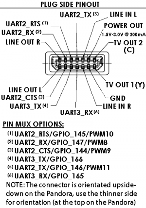
Ext Connector
What does it have?
- UART2
- UART3
- TV out
- Stereo line out
- Stereo line in
- The UART lines can also be used as GPIO (six of them) and PWM lines (four of them).
Where can we get the connectors from?
- The connector appears to be a Tyco Electronics connector, part number 1717169-2
- The manufacturer does *not* stock these for engineering samples, and very few vendors carry them
- Community member WizardStan has ordered a bunch and is selling them at $2 a piece plus shipping from Canada, see here (thread) or here (article)
How Do I Make a TV-Out Cable?
- There are some useful tips in the EXT Connectors thread.
- A guide explaining one way of creating the video cables can be found here
- MarkoeZ Has written a blog post about it here
Battery
- 3.7V
- Lithium polymer single cell battery
- 4000 mAH, 4 AH
- battery cover here: [2]
- reading out battery information: [[3]]
Internal connections
LCD
- TD043MTEA1 datasheet
- LTPS (8-bit parallel input for R, G and B, with separate horizontal and vertical sync)
- 3.0V
UART
- UART2 and 3 are available via the EXT connector, and via internal solder pads on the latest revision
- UART2 appears to support hardware flow control with RTS/CTS lines
- On the 2.6.27 Kernel UART3 is /dev/ttyS0
- On 2.6.37 or later, UART2 is accessible through /dev/ttyO1, UART3 is on /dev/ttyO2
GPIO
- 6 are available on the EXT connector
- 7 are internal, 2 of which can be used as extra shoulder buttons
- 1 located on the LCD cable
JTAG
- Yes, 1.8V 10-pin (board label JTAG)
I2C
- One at 1.8V from the OMAP (board label I2C3-1V8)
- One at 2.8V (board label I2C3-2V8)
USB
- No internal USB ports
Keypad backlight
- ?
Extra LEDs
LED7 and LED8 can be added. You need to add FETs (Q17 and Q18) and resistors (R165, R166, R167 and R168) See the official "Pandora Hacker Guide" from Michael Weston for more details and component values.
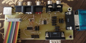
Breakout Board
This is the breakout board used by Pandora team members during development. Only a small number were made, and they are not available to the public. However a similar product (or gerber files) may be released in the future. A schematic for this board is available here: http://openpandora.ca/schematic/AV_Board_schematic.pdf


