Difference between revisions of "Hardware hacking"
From Pandora Wiki
(→UART) |
(→Ext Connector) |
||
| Line 4: | Line 4: | ||
=Pinouts= | =Pinouts= | ||
==Ext Connector== | ==Ext Connector== | ||
| − | '' | + | ''What does it have?'' |
| + | * UART2 | ||
| + | * UART3 | ||
| + | * TV out | ||
| + | * Stereo line out | ||
| + | * Stereo line in | ||
| + | * The UART lines can also be used as GPIO (six of them) and PWM lines (four of them). | ||
| + | |||
''What is the pinout?'' | ''What is the pinout?'' | ||
Revision as of 23:20, 9 February 2010
Contents
Making an RS232 level converter for the Pandora
How is this done?
Pinouts
Ext Connector
What does it have?
- UART2
- UART3
- TV out
- Stereo line out
- Stereo line in
- The UART lines can also be used as GPIO (six of them) and PWM lines (four of them).
What is the pinout?
- The pinout of the Ext Connector
Where can we get the connectors from?
Battery
3.7V Lithium polymer single cell battery 4000 mAH 4 AH battery cover here: [1]
Internal connections
Please add any information you have here
LCD
UART
UART2 and 3 are available via the EXT connector. UART2 appears to support hardware flow control with RTS/CTS lines on the EXT connector.
GPIO
Battery
JTAG
Keypad backlight
Maximum current draw?
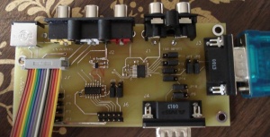
Breakout Board
This is the breakout board used by Pandora team members during development. Only a small number were made, and they are not available to the public. However a similar product (or gerber files) may be released in the future. A schematic for this board is available here: http://openpandora.ca/schematic/AV_Board_schematic.pdf
